In the Precision rectifier post, I gave the simplest circuit for making a precision rectifier:
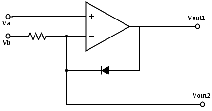
This circuit is both a log amplifier and a precision rectifier. If Vb is set to a constant voltage, then Vout1 varies as log(Vb–Va). Vout2 is max(Va,Vb).
The diode can be connected in the opposite direction, to get Vout2=min(Va,Vb) and Vout1 varying with log(Va–Vb).
And I showed the problem with this circuit at “high” frequency, as the slew rate limitations of the op amp limit the turn-on time (to about 8 µs):
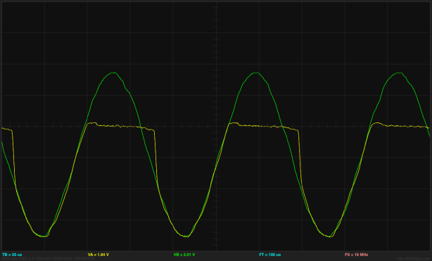
(click to embiggen) The S9018 NPN transistor with a 10kΩ resistor and a 15kHz input signal. The overshoot as the rectifier turns off is about 50mV, and the turn-on delay is about 8µsec. The turn-on delay does not vary much with the input resistance, unlike the turn-off overshoot.
I also promised, “There are standard solutions that limit the voltage swing, but I think I’ll leave that for a later blog post.” This is that post.
The textbook standard solution is to add another diode and resistor, and to configure the rectifier as an inverting amplifier (rather than a unity-gain one) when it is following the input:

Only one of D1 and D2 can be conducting.
This circuit has an input impedance of R1 (not the very high input impedance of the previous circuit). In this circuit, if Vin is more than Vthreshold, the output of the op amp goes low until diode D1 conducts and the negative input of the op amp is held at Vthreshold, as is Vout (with an output impdeance of R2). If Vin is less than Vthreshold, the output of the op amp rises until D2 conducts, and the feedback circuit makes an inverting amplifier with ")
We expect this circuit to have problems when neither D1 nor D2 is conducting—that is, as the circuit makes transitions between the rectifier being on or off. The simple rectifier circuit only had problems with turning on (as the op amp had to slew from a rail to a diode-drop past Vthreshold), but this improved circuit has to swing two diode drops when turning on or when turning off. The two-diode-drop swing is smaller than the
Here is an example of the output with a 30kHz clock, using S9018 transistors as diodes and R1 and R2 both at 10kΩ:

(click to embiggen) Output (yellow) for the improved rectifier with a 30kHz triangle wave as input (green). The glitches are about 140mV–160mV and last for about 4 µsec.
The duration of the glitches is always about 4µs, but the magnitude of the glitches depend very much on frequency. With a 2kHz triangle wave signal, I can’t see the glitches with the BitScope USB oscilloscope (so less than about 20mV). The magnitude of the glitch seems to be proportional to the input magnitude. Using a constant amplitude triangle wave input (about 2.6v peak-to-peak), I measured the glitches for some higher frequencies:
| frequency | positive glitch | negative glitch |
|---|---|---|
| 3kHz | 40mV | 40mv |
| 10kHz | 80mV | 80mv |
| 20kHz | 120mV | 100mv |
| 30kHz | 160mV | 140mv |
| 40kHz | 200mV | 180mv |
| 50kHz | 220mV | 210mv |
| 60kHz | 250mV | 260mv |
| 70kHz | 260mV | 300mv |
To understand where the glitches come from, it helps to look at the op-amp output and the negative feedback input:

(click to embiggen) The output of the op amp (green) is either a diode drop above or a diode drop below the output of the rectifier circuit (yellow) depending which diode is conducting. The transitions between these states are limited by the op amp slew rate. I measured about 600 mV/µsec, which is what the MCP6002 op amp I’m using is specified to have as a slew rate (I measured before looking it up, to keep from being biased by the “correct” answer).

(clcik to embiggen) The negative input of the op amp (green), which the feedback circuit is trying to keep at Vthreshold, has glitches when the op amp output (yellow) is ramping between its two states.
The glitches in the improved circuit are smaller than for the simpler circuit, and can be further reduced by using Schottky diodes (to reduce the size of the diode drop, and hence how far the op amp must swing to change states) or a faster op amp (to reduce how long the op amp takes to slew the two diode drops). I expect that with the Schottky diodes, the glitches should be reduced to 2(450mV)/(600 mV/µs)=1.5µs. Since the glitches are basically triangular pulses, reducing the duration by a factor of 2–3 should reduce the amplitude by as much, and the total energy by 8–27.
To test the rectifier circuit with better diodes, I’ve ordered some 1N5817 Schottky diodes from Digi-key. I like dealing with that company, as they have a lot of components I need, are always very fast in processing orders, and have not yet messed up an order. They were once out of stock on something that I had ordered, and called me up to apologize profusely for the mistake in their inventory database (normally they notify you before you order if something is out of stock). For today’s order, they sent me notice that they had shipped the order less than an hour and a half after I had placed the order. Because they offer first-class US mail as a shipping option, their shipping charges tend to be much less than most of the places I deal with. (UPS ground is cheaper for big things, but no one is beating the Post Office prices on small lightweight objects.)
Disclaimer: neither Digi-key nor the Post Office has offered me anything for my endorsement—I’m just feeling pleased with them right now.
Filed under: Circuits course, Data acquisition Tagged: BitScope, Digi-key, op amp, rectifier

